
On this page
- Diagnosis summary
- Safety and classification scope
- Definition (Reference)
- Typical Presentation (Informative)
- Field Identification Cues (Normative)
- Classification Mapping (to VIS-DA) (Normative)
- Indicative Depth / Relief (Informative)
- Evidence Package (Documentation Requirements) (Normative)
- Mis-ID Pitfalls (Informative)
- Reporting Language (Template)
- Related glossary terms
- Related DSS
- Source and version
DAMAGE SPECIFICATION STANDARD / METHOD-AGNOSTIC
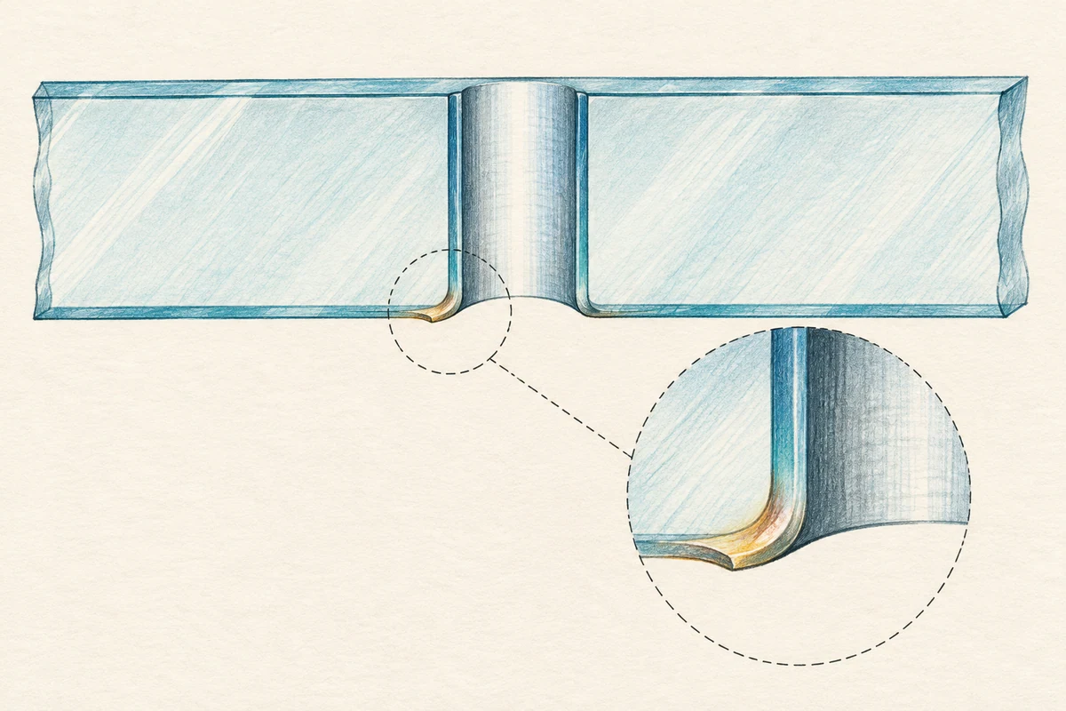
DSS-P.03.04 — Drill/Slot “Exit Lip” (acceptable edge artifact)
Fabrication & finishing - reference; generally not “damage” unless it propagates onto the face
Diagnosis summary
A localized burr/lip at the exit of a drilled hole or machined slot produced during fabrication when the tool breaks through the ply. Typically confined to the edge of the hole/slot or immediately adjacent edge land, not onto the visible face. Considered a factory edge artifact rather than a worked-surface defect when it does not create a face-side transition edge or chip-flank morphology.
Definition (Reference)
ReferenceA localized burr/lip at the exit of a drilled hole or machined slot produced during fabrication when the tool breaks through the ply. Typically confined to the edge of the hole/slot or immediately adjacent edge land, not onto the visible face. Considered a factory edge artifact rather than a worked-surface defect when it does not create a face-side transition edge or chip-flank morphology. Evaluate under VIS lighting/geometry; factory acceptance remains distinct from post-restoration acceptance governed by VIS.
Typical Presentation (Informative)
Informative- Narrow circular or crescent lip on the exit side of a hole; short linear lip at a slot exit.
- May look matte (micro-ground) or slightly glossy (tool burnish).
- Often only visible in raking/oblique views; no effect on the broad face. Use VIS §5 geometry.
Field Identification Cues (Normative)
NormativeSurface-catch class (MSRT):
- On the face adjacent to the feature: record SC-0 (none)-one light, non-marring pass per VIS §5.5; do not abrade or repeat. On coated faces, prefer a polymer stylus and default to visual cues if any coating risk exists.
Visual signature:
- Edge-confined lip at a hole/slot exit with no transition edge on the face; no pits/craters; no bright chip flanks on the face. If chip flanks (micro-chipping) are present on the face, evaluate under edge/corner or drilling-related damage families.
Viewing/lighting:
- Inspect at 12 / 36 / 72 in using normal + oblique sweep (~60°-120°) with raking light; surfaces clean/dry per reveal. Location/access:
- Log pane ID and surface numbering (#1-#4; laminate-internal); acceptance pertains to the exposed surface under evaluation.
Classification Mapping (to VIS-DA) (Normative)
Normative- Processing feature - not surface damage. When the lip is confined to the hole/slot exit and adjacent edge land with SC-0 on the face and no worked perimeter, record “Processing Feature - Not Surface Damage (outside CAT-1...CAT-4).”
- Escalate when:
- Face-side micro-chipping or chip flanks propagate from the exit → classify by morphology under M.03 Edge & Corner or M.06 Drilling/Notching-Related at CAT-3/4 (clear catch; rough flanks; pits/craters).
- Crack initiation (edge-origin or through-thickness) is observed → document under M.07 Cracking & Fracture; CAT-5 if condition is structural/inaccessible for in-place work.
- Between-pane indication (fixed parallax in IGU cavity) → CAT-5 by location/condition; refer per project protocol.
Indicative Depth / Relief (Informative)
Informative- The lip is an edge geometry artifact; on the face it typically registers SC-0 (no tactile relief). If face micro-chips are present, they correlate with clear catch and bright flanks (trend CAT-3 → CAT-4 by morphology), not with a uniform “lip.” Differentiation & False Positives (Informative)
- vs. Edge micro-chipping (M.03): Micro-chips show discrete shelling and bright flanks; an exit lip is a continuous burr localized to the hole/slot perimeter. Escalate only if chips propagate onto the face.
- vs. Linear scoring (M.01): Scoring forms extended lines across the face and often shows clear catch; an exit lip is peripheral to a hole/slot.
- vs. Coating anomalies (Co.01/Co.03): Coating rub/patchiness is localized on the worked surface and disallowed at acceptance on coated faces; an exit lip is an edge fabrication artifact. Apply §6.2.e when coatings are present.
Evidence Package (Documentation Requirements) (Normative)
Normative- Photo set (VIS): 12 / 36 / 72 in, normal + oblique; include raking macros showing the exit perimeter and a context frame confirming the lip is edge-confined (no face perimeter/transition edge).
- MSRT result: Record SC-0 on the face; one pass only, non-marring; on coated faces, prefer polymer stylus.
- Forms: Pane ID; product family + surface numbering; worked surface Y/N; functional coating present on worked surface? (Y/N/Unknown); reveal status; lighting/time; geometry checklist; photos attached.
- Acceptance split: VIS governs post-restoration appearance; do not conflate a factory exit lip with face-side acceptance requirements. (If restoration is performed near holes/slots, transition edges and chip flanks remain disqualifying for CAT-0...CAT-4.)
Mis-ID Pitfalls (Informative)
InformativeAttempting to “blend off” a factory exit lip onto the face can create a worked region with a visible transition edge, which VIS disallows at acceptance. Keep classification appearance-only unless face damage exists; then classify by the appropriate M-series entry.
Reporting Language (Template)
Template- P.03.04 Drill/Slot Exit Lip (Processing Feature) - Localized exit-side burr/lip confined to the hole/slot perimeter; MSRT on face = SC-0 (no relief). No transition edge or chip-flank morphology on the face. Recorded as manufacturing edge artifact; not categorized as surface damage under VIS-DA. If face micro-chipping or cracks are present, classify under M.03/M.06/M.07 by CAT; if between-pane cues exist, record CAT-5 and refer per protocol.
Related glossary terms
- ChipGRK-034
- Raking lightGRK-129
- Coating rubGRK-115
Source and version
GlassRenu Damage Specification Sheets (DSS), DSS-P.03.04. Source revision and extraction date are recorded in the deployment manifest.
Open the complete published DSS with table of contents (PDF)
Normative and informative labels are preserved from the source. The downloadable one-sheet is a condensed classification aid; this web page retains the complete source-based specification content.