
On this page
- Diagnosis summary
- Safety and classification scope
- Classification & Scope (Normative)
- Typical Presentation (Informative)
- Field Identification Cues (Normative)
- Surface-catch class (MSRT)
- Visual signature
- Viewing / lighting
- Location / access
- Mechanism cue (context)
- Severity & CAT Mapping (Normative)
- Differentiation & Mis-ID Pitfalls (Informative)
- Evidence Package *(Documentation Requirements) (Normative)
- Reporting Language (Template)
- ⭐ DSS-M
- Damage Specification Standards 2026
- DSS-M Mechanical Abrasion/Scoring/Impact/Cracking
- Draft v1.0
- M.01 Linear Scoring / Tracks
- M.02 Abrasion Fields (Non‐linear)
- M.03 Edge & Corner Damage
- M.04 Impact & Contact
- M.05 Fabrication Debris (FD) Scratches
- M.06 Drilling/Notching‐Related
- M.07 Cracking & Fracture (mechanically initiated)
- Related glossary terms
- Related DSS
- Source and version
DAMAGE SPECIFICATION STANDARD / METHOD-AGNOSTIC
DSS-Co.05.03 — Frit Over-Spray / Edge Ghost
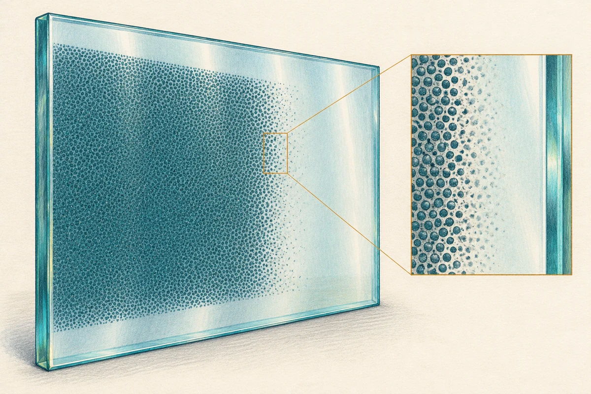
Ceramic frit anomaly - faint halo, fog, or particulate fringe extending beyond the intended frit boundary after application/firing; reads through glass from the viewing side; typically SC-0 at the viewing face. Confirm frit face, mask lines, and artwork intent before attribution.
Diagnosis summary
Frit over-spray / edge ghost is an appearance change where fine frit particulates or mist extend just outside the intended frit edge (mask/screen boundary), producing a narrow, edge-parallel halo or ghost fringe after firing. The condition is planar within the fired frit layer (usually on #2 or #4) and non-tactile from the viewing surface. Classification is appearance-only per VIS (method-agnostic).
Classification & Scope (Normative)
NormativeFrit over-spray / edge ghost is an appearance change where fine frit particulates or mist extend just outside the intended frit edge (mask/screen boundary), producing a narrow, edge-parallel halo or ghost fringe after firing. The condition is planar within the fired frit layer (usually on #2 or #4) and non-tactile from the viewing surface. Classification is appearance-only per VIS (method-agnostic). Inspect after Non-Invasive Reveal at the viewing face under VIS lighting/geometry; record surface numbering and worked-surface status.
System ID is critical. Verify frit location (surface #), edge geometry (straight/curved, corner details), mask/artwork specification, and intended edge tolerance from shop drawings/submittals.
Typical Presentation (Informative)
Informative- Narrow halo band (commonly 1-8 mm) immediately outside the frit edge; density decays with distance from the edge.
- Uniform along long edges or localized at corners/start-stop zones; may show fine “sparkle” under raking from micro-particulate in the halo.
- Often lot-repetitive along identical edges, indicating process origin (mask leakage/spray plume).
Field Identification Cues (Normative)
NormativeSurface-catch class (MSRT)
- From the viewing (glass) side: SC-0 (planar defect behind the glass).
- Do not MSRT the frit face in situ. MSRT supports classification only on the viewing surface.
Visual signature
- Edge-parallel fringe/gradient following the exact frit perimeter; no chip-flank sparkle, no grooves/pits at the viewing face.
- Gradient profile: highest density at frit boundary, dissipating outward; no ring/run geometry.
Viewing / lighting
- Evaluate clean & dry at 12 / 36 / 72 in, normal and oblique sweep (~60°-120°); use raking macros across the edge transition and broad specular to show halo gradient. Record distances/angles in-frame.
Location / access
- Record pane ID and surface numbering (#1-#4; laminate-internal). If frit is on #2/#3 (IGU interior) or otherwise non-exposed, in-place correction is out of scope → CAT-5 by location (classification remains Co.05.03).
Mechanism cue (context)
- Mask leakage, spray plume beyond mask, screen bleed at edge, electrostatic drift, or pre-fire handling shedding near boundary. Consistency along identical edges supports process attribution.
Severity & CAT Mapping (Normative)
NormativeAssign CAT by visibility at acceptance geometry and halo prominence/extent. Depth values are apparent optical, not substrate relief.
- CAT-1 (Benign / non-relief): Very faint halo legible mainly at oblique/raking; halo width ≲ 2-3 mm; SC-0 viewing face.
- CAT-2 (Light): Discernible fringe at standard distance in common lighting; halo width ~3-6 mm or moderate density along limited lengths; SC-0.
- CAT-3 (Moderate): Pane-noticeable halo at standard distance along long edges/corners, width ≳ 6-8 mm or high density compromising edge crispness over ≥0.5% of visible field; SC-0.
- Reclassify when:
- Cloud-like opacity shifts without edge-parallel geometry → Co.04.01 Mottle/Cloudiness.
- Loose paint on viewing face lifts on reveal → R.02.01 Paint overspray film.
- Front-face grooves/pits/fused nodules → consider M/Th families.
- CAT-5 (by condition/location): Between-pane/inaccessible frit face or system constraints preclude in-place work → CAT-5.
CAT is appearance-based; acceptance is separate under VIS-A §6 at 12/36/72 in.
Differentiation & Mis-ID Pitfalls (Informative)
Informative- vs. Roller pickup (Co.02.01): Roller ghosting shows panel-spanning parallel bands at fixed pitch, not edge-tied halos.
- vs. Back-paint edge fog (Co.04.01): Similar halo can occur in back-paint; confirm system and face to avoid mis-attribution.
- vs. Chemical halos (Ch family): Chemistry presents rings/runs/wetting geometry and may yield SC-1/2; Co.05.03 is edge-parallel, ringless, and SC-0 at the viewing face.
- vs. Frit smears/offset (Co.05.01): Smears/offset impact the artwork edge itself (drag/registration); Co.05.03 is a separate fringe outside the intended boundary.
Evidence Package *(Documentation Requirements) (Normative)
Normative- Photo set (VIS): 12 / 36 / 72 in, normal + oblique; raking macros across the edge transition; overview frames showing edge length and uniformity. Record distance/angle in-frame.
- System ID. Confirm frit face, mask/artwork specification, lot/date; obtain shop drawings/submittals if available.
- MSRT (viewing face). Record SC-0 to distinguish from front-face mechanical/chemical attack.
- Lot/replication check. Survey adjacent units/edges for repeatability (supports process origin).
- Forms: Pane ID; surface numbering & worked-surface status; reveal status; lighting/time; geometry checklist; photos attached.
- Acceptance split: Post-restoration acceptance per VIS-A §6; classification ≠ acceptance.
Reporting Language (Template)
Template- Co.05.03 Frit Over-Spray / Edge Ghost - Edge-parallel halo/fringe beyond frit boundary on surface #___ (frit face confirmed); MSRT (viewing face): SC-0; visible at [12/36/72 in] under VIS geometry (oblique/raking most legible). Morphology: gradient fringe, no chip-flank grooves/pits at viewing face. Classification: CAT-[1/2/3] by visibility/extent; CAT-5 if between-pane/inaccessible. Forms + photo set attached; acceptance per VIS-A §6.
⭐ DSS-M
Damage Specification Standards 2026
DSS-M Mechanical Abrasion/Scoring/Impact/Cracking
Draft v1.0
M.01 Linear Scoring / Tracks
- M.01.01 Scraper/razor scoring
- M.01.02 Straightedge/metal guide scoring
- M.01.03 Glass‐on‐glass track (paired arcs/lines)
- M.01.04 Conveyor/belt line scoring (handling line)
- M.01.05 Hardware/fastener drag line
M.02 Abrasion Fields (Non‐linear)
- M.02.01 Micro‐abrasion swirls / pad trails
- M.02.02 Cross‐hatch scuffing / sanding pattern
- M.02.03 Directional webbing (repetitive paths)
- M.02.04 Burnish/haze field (localized over‐polish)
- M.02.05 Squeegee burn lines (friction film)
M.03 Edge & Corner Damage
- M.03.01 Edge micro‐chipping (minor)
- M.03.02 Edge gross chipping / clamshell
- M.03.03 Corner crush / corner spall
- M.03.04 Edge “shelling” at hardware holes/slots
M.04 Impact & Contact
- M.04.01 Impact divot (non‐through)
- M.04.02 Star break / bullseye initiation (annealed/laminated)
- M.04.03 Pellet/BB impact signature
- M.04.04 Tool strike / ladder foot imprint
- M.04.05 Hardware contact rub (spider/rail fittings)
M.05 Fabrication Debris (FD) Scratches
- M.05.01 Short FD scratch cluster
- M.05.02 Long FD scratch field
- M.05.03 Wash‐line scratch bands
M.06 Drilling/Notching‐Related
- M.06.01 Hole edge micro‐chips (excess)
- M.06.02 Notch root micro‐cracks
M.07 Cracking & Fracture (mechanically initiated)
- M.07.01 Edge‐origin stress crack (chip origin)
- M.07.02 Through‐thickness crack propagation
- M.07.03 Fragmentation pattern (tempered fracture documentation)
Related glossary terms
- Paint oversprayGRK-063
- RepeatabilityGRK-150
- Scratch fieldGRK-108
- AbrasionGRK-035
- ScratchGRK-032
Source and version
GlassRenu Damage Specification Sheets (DSS), DSS-Co.05.03. Source revision and extraction date are recorded in the deployment manifest.
Open the complete published DSS with table of contents (PDF)
Normative and informative labels are preserved from the source. The downloadable one-sheet is a condensed classification aid; this web page retains the complete source-based specification content.