
On this page
- Diagnosis summary
- Safety and classification scope
- Definition (Reference)
- Typical Presentation (Informative)
- Field Identification Cues (Normative)
- Surface-catch class (MSRT)
- Visual signature
- Viewing / lighting
- Location / access
- Classification Mapping (to VIS-DA) (Normative)
- Indicative Relief (Informative)
- Differentiation & False Positives (Informative)
- Evidence Package (Documentation Requirements) (Normative)
- Reporting Language (Template)
- ⭐ DSS-A
- Damage Specification Standards 2026
- DSS-A Assembly/Internal Conditions
- Draft v1.0
- A.01 IGU Cavity & Seal
- A.02 Laminated Glass Interlayer
- A.03 Mirrors & Back‐Coated Products
- A.04 Switchable/Smart Glazing (PDLC/EC)
- Related glossary terms
- Related DSS
- Source and version
DAMAGE SPECIFICATION STANDARD / METHOD-AGNOSTIC
DSS-P.04.04 — Curved/Bent Glass Local Thickness / Thinning Signatures
Specialty/Decorative systems - reference; generally not “damage”
Diagnosis summary
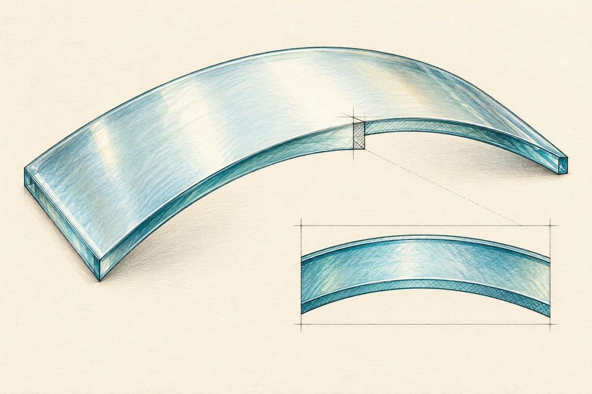
Curved/bent glass local thickness/thinning signatures are pane-scale shape and thickness variations inherent to thermal bending/forming. They can present as subtle local thinning or thickening zones (e.g., at tight radii or near quench/bend tooling influence) that modulate reflections/transmission without forming a worked perimeter on the exposed face. These are manufacturing attributes observed under VIS geometry;
Definition (Reference)
ReferenceCurved/bent glass local thickness/thinning signatures are pane-scale shape and thickness variations inherent to thermal bending/forming. They can present as subtle local thinning or thickening zones (e.g., at tight radii or near quench/bend tooling influence) that modulate reflections/transmission without forming a worked perimeter on the exposed face. These are manufacturing attributes observed under VIS geometry; post-restoration acceptance of worked areas remains separate from factory product acceptance.
Typical Presentation (Informative)
Informative- Angle-dependent optical effects in reflected/transmitted views near bends/radii: mild brightness roll-off, localized “soft” reflective warps, or slight magnification/minification zones tied to bend geometry-no transition edge on the face.
- May co-occur with heat-treat signatures (e.g., roller/bearing influence) on bent tempered product; read strongest in raking/oblique views. Use the same VIS geometry applied to roller-wave/bow documentation.
Field Identification Cues (Normative)
NormativeSurface-catch class (MSRT)
- SC-0 (none) at the exposed face. Make one light, non-marring pass per VIS §5.5 to confirm no local relief; MSRT supports classification only (do not abrade).
Visual signature
- Pane-scale, non-perimeter optical shape/thickness effects contiguous with the bent geometry; no chip flanks, pits/craters, and no worked transition ring on the clear face. Use straight-line reflections (mullion/string-line/horizon) to show bending/size change across the area.
Viewing / lighting
- Evaluate clean & dry at 12 / 36 / 72 in, normal incidence and oblique sweep (~60°-120°) with raking light, per VIS.
Location / access
- Record pane ID and surface numbering (#1-#4; laminate-internal) on forms when IGUs/laminates are present.
Classification Mapping (to VIS-DA) (Normative)
Normative- Processing/design feature - not field damage. If observation confirms SC-0 with pane-scale optical/shape effects and no local relief, record “Processing Feature - Not Surface Damage (outside CAT-1...CAT-4).” VIS keeps classification separate from acceptance; reserve CAT-5 for between-pane/inaccessible conditions by parallax/location.
If factory flatness/optical distortion must be quantified for product acceptance, refer to product specifications (e.g., ASTM C1036/C1048) and optical distortion background (ASTM C1651, informative). VIS governs post-restoration appearance only.
The Glass Restoration Standards...
Indicative Relief (Informative)
Informative- N/A as local relief. Local thickness/shape in bent glass is a product attribute; at the exposed face it does not present as a localized, MSRT-detectable relief feature. (Optical/flatness context aligns with VIS’s use of C1651 informatively for heat-treated distortion phenomena.)
Differentiation & False Positives (Informative)
Informative- vs. Roller wave (P.01.01): Roller wave is periodic flatness deviation from heat-treat; bent-glass thickness signatures are geometry-driven and track the bend radius, both SC-0 at the face. Use straight-line reflections to distinguish periodic vs geometry-tied shape.
- vs. Abrasion fields (M.02): Abrasion shows directional patterning and can escalate to slight/clear catch; bent-glass thickness signatures remain SC-0 and lack a worked boundary.
- vs. Coating anomalies (Co.01/Co.03): Coating rub/patchiness is localized and disallowed at acceptance on worked coated surfaces; geometry-driven thickness signatures are pane-scale, no perimeter, SC-0.
Evidence Package (Documentation Requirements) (Normative)
Normative- Photo set (VIS): 12 / 36 / 72 in; normal + oblique; include raking macros as needed; capture a straight-line reflection frame (mullion/string-line/horizon) across the bent zone to show optical/size change. Record distance/angle in-frame.
- MSRT result: Record SC-0 (one light, non-marring pass; do not abrade).
- Forms: Pane ID; product family + surface numbering; worked surface Y/N; functional coating present on worked surface? (Y/N/Unknown); reveal status; lighting/time; geometry checklist; photos attached.
- Acceptance split: Document per VIS; factory acceptance (flatness/optical) is governed by product standards/specs; do not conflate with post-restoration appearance rules.
Reporting Language (Template)
Template- P.04.04 Curved/Bent Glass - Local Thickness/Thinning Signatures (Processing Feature) - Pane-scale, geometry-tied optical/shape effect observed at VIS geometry (12/36/72 in; normal + oblique; raking). MSRT = SC-0 (no relief). No transition edge or chip-flank/pit morphology on the exposed face. Recorded as manufacturing attribute - not surface damage under VIS-DA. If fixed parallax indicates a between-pane look-alike, record CAT-5 and refer per protocol. Acceptance of any worked area per VIS §6; factory product acceptance per ASTM C1036/C1048 (optical-distortion background ASTM C1651, informative).
⭐ DSS-A
Damage Specification Standards 2026
DSS-A Assembly/Internal Conditions
Draft v1.0
A.01 IGU Cavity & Seal
- A.01.01 Internal haze/volatile fogging (#2/#3)
- A.01.02 Moisture/condensation between panes (#2/#3)
- A.01.03 Desiccant dust/fines in cavity
- A.01.04 Spacer smear/bleed inside cavity
- A.01.05 Low‐E surface corrosion within cavity
- A.01.06 Breather tube/altitude tube staining pattern
A.02 Laminated Glass Interlayer
- A.02.01 Edge haze/whitening (PVB/ionoplast)
- A.02.02 Bubbles/stringers (entrapped gas/voids)
- A.02.03 Contamination inclusions in interlayer
- A.02.04 Interlayer creep/exudation at edge
- A.02.05 Interlayer discoloration/yellowing (UV/thermal aging)
- A.02.06 Local delamination (ply/interlayer separation)
A.03 Mirrors & Back‐Coated Products
- A.03.01 Mirror edge blackening (back‐coating corrosion)
- A.03.02 Spot corrosion behind mirror
- A.03.03 Adhesive/chemical attack from behind
A.04 Switchable/Smart Glazing (PDLC/EC)
- A.04.01 Black spots/voids in active layer
- A.04.02 Busbar/lead defects visible through lite
Related glossary terms
- Laminated glass interlayerGRK-223
- Optical distortionGRK-117
- Glass restorationGRK-161
- Laminated glassGRK-009
- MagnificationGRK-132
- Raking lightGRK-129
- Coating rubGRK-115
- DesiccantGRK-220
Source and version
GlassRenu Damage Specification Sheets (DSS), DSS-P.04.04. Source revision and extraction date are recorded in the deployment manifest.
Open the complete published DSS with table of contents (PDF)
Normative and informative labels are preserved from the source. The downloadable one-sheet is a condensed classification aid; this web page retains the complete source-based specification content.